Hopper inserts, an approach to solving poor flow
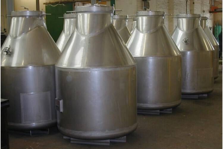
Enhanced hopper performance through sustained examination of materials, hopper geometries and influence of insert design. The enormous volume of bulk materials handled every year means solids must be stored in hoppers, intermediate bulk containers, silos and other storage devices, often several times before being processed.
However, storage can result in a number of handling issues including erratic surges, arching, ratholes, packing, flushing, dead regions, feed upsets, and in some cases can reduce the suitability of the product for the next process stage
[IMG02**R45]
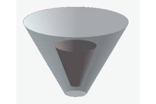
Although it is seemingly counterintuitive to introduce an obstacle into the storage container as a solution to these problems, the use of inserts can enhance storage container performance.
An insert is usually a static fitting on the inside of a bulk storage container, including liners and other modifications that alter the internal space of a vessel. Flow regimes are determined by how the individual particles in a bulk solid respond to local forces at contact points. An insert alters the flow regime of a material…


")